Easier to Build
Rotary Spark Gap Designs
by
Terry Blake
(01/31/04)
Motor Requirements
I began this rather esoteric hobby about April, 2001, after discovering eBay and finding that things like Tesla coils (and components) could easily be purchased online. Since then, I wanted to try everything as fast as possible, to get a better idea of what was best.
I started with static gaps and small coils, and wanted to work my way up quickly to the larger coils (I am at 7.5 KVA so far). I wanted to try 120, 240, 360, and 480 BPS synchronous, and also asynchronous rotary spark gaps. As I looked into the rotary spark gap designs being used, it quickly became apparent that these were not gonna be easy to build.
The synchronous stuff requires pulling the motor apart and grinding flats on the sides of the armature. I tried this, but the effort was a pain (even for a small sized motor), and the results were not that good. It did not lock with the rotor mass in place. Bugger. Need a bigger motor. Lots more grinding.
The asynchronous motors do not require modification, but getting one of decent size is expensive. The Ed Wingate motor of choice is a Dayton model #2M145 which is a 1/2 HP 0-10000 RPM, ball bearing, AC-DC 120V Universal motor with a 3/8" shaft. The current price from Graingers is $136.00. They aren't cheap, but he has used this motor on dozens of 10" rotary gaps with zero problems.
Ed's rotary gaps are very impressive. But I don't have the tools to build that kind of equipment. Yet.
Ed Wingates Tesla Coils and Rotary Spark Gaps
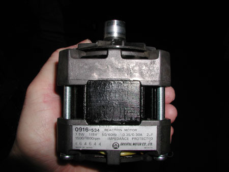
There are small 1800 RPM synchronous motors readily available from various
sources for $5-$10. They could make a great 1800 RPM SRSG, if the rotor was not too hard to spin.
Herback and Rademan http://www.herbach.com/
TM91MTR1751 (pg 6 of Y2000 catalog)
American Science and Surplus http://www.sciplus.com/
22602 SHINANO TOKKI MOTOR
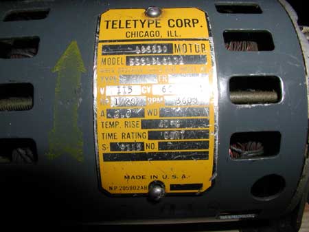
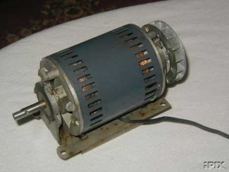
If you keep your eyes open, you can find Teletype motors commonly available on eBay for $10-$20.
They are 1/20 HP and synchronous at 3600 RPM. No motor modifications required.
The phase is adjustable by rotating the motor in the mount. Very cool.
There are also small asynchronous motors available for a low cost.
American Science and Surplus http://www.sciplus.com/
A universal ball bearing vacuum cleaner motor.
120 V, AC/DC, 15,000 rpm, 30599 VACUUM MOTOR $7.50
There are some cheap motor options available. But they can't spin the typical rotor.
Simplified Rotor Design
The problem is the heavy rotor design. It is made of G10 for strength and electrical isolation from the motor. G10 can be hard to work with, and burns up blades and drills. You need an arbor to connect it to the motor shaft. You need a metal ring to interconnect the electrodes (on some designs). You need to make electrodes from Tungsten (typical), which is even harder to work with. Don't forget your electrode holders or maybe set screws in your 1/2" thick rotor. Then you have to balance it on your big motor.
The folks on the Tesla Mailing list suggested there was no advantage to a round disk.
They suggested a square plate with electrodes in the corners.
Some rotor designs had only 1 or 2 electrodes in the entire disk.
That seems like a big waste of the disk. You could cut away most of it and it would still work.
Maybe instead of a disk, just a strip or rod of G10 with electrodes in the ends (from McMaster-Carr)?
Tesla Coil Mailing List: The Users Group for active coilers. Email based, so it comes to you. http://www.pupman.com/
McMaster-Carr http://www.mcmaster.com/
While working on the G10 rod design, it was noticed that the 7" electrodes were already spanning the entire distance the G10 rod was to cover.
But how to connect the electrode to the motor without making electrical contact?
A polyethylene arbor (from McMaster-Carr).
The difficulty is to drill a hole for the shaft and a hole for the electrode, perpendicular to the material and each other.
Maybe you laugh, but without a nice drill press (mine is a $50 special from Menards) and one of those square vise clams things, and other stuff like that, it is very hard.
I know, everything's too hard for me. Whine whine whine.
I ultimately bought one of those Craftsman Drill Guides from Sears for $26.99, and life has been a lot better.
In fact, I have been using this drill guide a lot and I am very happy with it.
Even though it does not look exactly like the photo given on the sears web site.
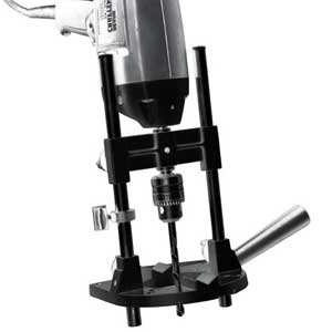
With the drill guide and a little holding jig (two square lengths of hardwood and some C-clamps), I could make the arbor.
One thing I noticed about the polyethylene, when you drill a hole, it often ends up smaller than your drill. This is actually good, because the rod or shaft is held very tightly in place. So much so, that I have to beat the electrodes in place with a 2x4 (a metal hammer tends to mushroom the electrode ends). They do not appear to need a set screw, as I cannot move them with my bare hands. If you have any doubt about the fit of your electrode or shaft, make sure you use a set screw, drill a smaller hole, or use shaft collars.
How tight it should be? I found it took over 20 pounds to move the electrode (measured with a bathroom scale). See the safety issues below.
So here is what it looks like. My simplest rotor design.
Parts: a 2" long piece of 1" square polyethylene rectangular bar (McMaster-Carr 8702K122 - UHMW Polyethylene)
and a 5/32" thick, 7" long Tungsten electrode (McMaster-Carr 8000A72 - Pure Tungsten Electrode - 5/32")
That's it.
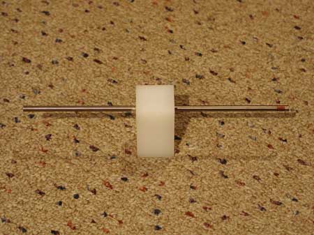
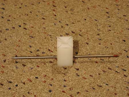
All you have to do is drill a hole for the electrode and hole for the shaft.
Try to be as centered and square and perpendicular as you can. Everything helps.
THE HOLES CANNOT INTERSECT
The shaft hole cannot get closer than 1/8" from the electrode hole, or you will not have electrical isolation (BAD).
Make sure to get as much polyethylene between the electrode and the motor shaft as you can.
A minimum of 1 inch linear distance along arbor.
The high voltage will try to take the shortest route it can find.
You should take the sharp edge off one end of the electrode (slight rounding with a grinder) before you insert it in the arbor.
It makes insertion a lot easier and prevents the edge from scraping off some of the inside of the hole, which will reduce the tight fit.
Drive the electrode into the arbor, and try to get it centered. Use a 2x4 to avoid mushrooming of the electrode.
Put it on the motor and spin it, to determine if the electrode is truly centered WWT the shaft.
Use a stationary object (like maybe a stationary electrode) to compare both ends of the rotor electrode for alignment.
Adjust as necessary, and things will automatically be in very good balance.
OK. Now your done with that part. It hardly hurt a bit (drill bit that is), and no Tungsten cutting required.
So what do you have? You have a very light weight rotor that is in balance and spans 7".
It is similar in many ways to an 8" diameter, 1/2" thick, G10 disk with 2 electrodes spaced 180 degrees apart and 1/2" from the edge.
The design includes the electrode holders and arbor you would have to make or get.
I have not seen this design anywhere else and believe it to be a new idea.
Do you like it?
I have not had any problems with these designs and no problems have been reported to me. I have been very carefull, use enclosures, and constantly double check everything. But as with any rotary spark gap, you should be concerned about your safety. With this design, if the rotor is not well balanced or not tight, it may pull out of the arbor and collide with the stationary electrodes. The shrapnel will be deadly. I expect you to use an enclosure of some type. A 3/4" plywood box is minimum required protection. Please review the safety issues to get a better understanding of what I look at and may be a problem for you.
Safer Rotor Design
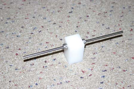
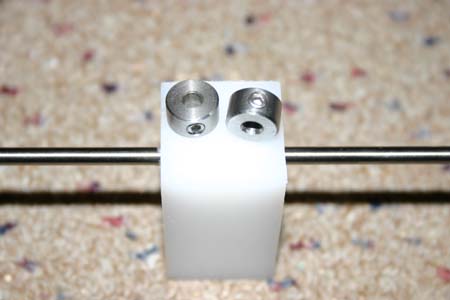
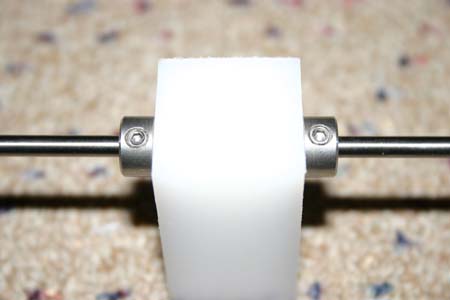
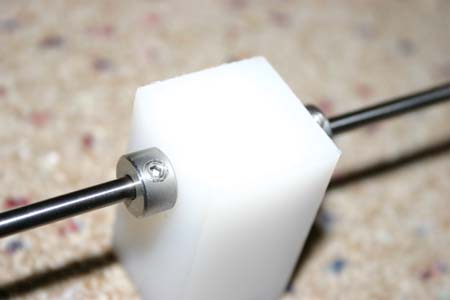
This a change to the rotor design that is directed at improved safety, while maintaining simplicity. The idea is keep the electrode from moving by using shaft collars with set screws. You can get these from McMaster-Carr. They come in various flavors. The smaller and lighter, the better. I tried these steel shaft collars with a single set screw. I slid a board onto the electrode and put my whole weight on the shaft collar. I was not able to get the collar to move at all. I am around 180 pounds, so these things can really hold tight.
But like any screw, they can get loose. If they get loose, the shaft collar will fly off the electrode and cause shrapnel. So you will have to check these from time to time or use locktight on the threads. Maybe the locktight could be applied to the junction of the shaft collar and the electrode, cementing them in place. Some people may even want to file an indent in the electrode where the set screw touches to improve grip.
This does not make the enclosure any less necessary, but eliminates the issues that result in a loose electrode sliding out.
*** KEEP THOSE SET-SCREWS TIGHTENED ***
Complete Rotary Spark Gap Designs
So you have the rotor. Now what do you do.
These are the complete designs I have come up with so far.
Gary Lau has referred to these as a propeller-style RSG construction.
I kinda like that description.
I hope that these designs make it possible for many more people to enjoy a rotary spark gap of their own.
Don't forget to be safe. If the spinning electrode hits a stationary one, the shrapnel will be deadly.
Make an enclosure of some type.
A 3/4" plywood box is minimum required protection.

1800
RPM Synchronous Rotary Spark Gap
(03/16/02)

Asynchronous Rotary Spark Gap
(06/27/02)
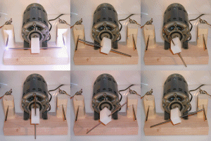
3600 RPM 120 BPS Synchronous Rotary Spark Gap
(08/20/02)
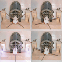
3600 RPM 240 BPS Synchronous Rotary Spark Gap
(08/20/02)
Other
Rotary Spark Gaps
(03/29/02)
A Mid-Sized Tesla Coil using these
Rotary Spark Gaps
(08/24/02)
A HUGE-Sized Tesla Coil using these
Rotary Spark Gaps
(06/30/02)
Tell me what you think about all this stuff.
home@tb3.net
Coilers Using a TB Inspired
Rotary Spark Gap Design
Kent Tinsley
(01/23/03)
Daniel McCauley
(01/23/03)
Stephen Conner
(01/23/03)
Steve Ward
(10/26/03)
Gary Lau
(06/13/04)