![]()
The simple static gap fires randomly at various voltages and phases
of the AC wave form, thus making the Tesla Coil sound like random white
noise or buzzing.
The SRSG provides a way to fire the Tesla Coil at the exact same position (phase) of the AC wave form, every time. This allows the capacitor to charge up to the exact same voltage (typically the maximum is used), before the gap is fired. The break rate of the spark gap is exactly 120 times per second. This results in maximum consistent bang size and a very tonal sound from the Tesla Coil (like 120 Hz -ish).

Here is an excellent example of a synchronous rotary spark gap that
uses a 1/50th HP 1800 rpm sync motor, and a 5.125" disk rotor. This
SRSG was made by John
Freau for use on his TT-42 table top Tesla coil. There are 2
stationary electrodes and a rotating disk with 4 interconnected electrodes
near the edge (90 degree spacing).
Synchronous motors are hard to find. Many people buy a non-synchronous motor and make it synchronous. This is done by taking the motor apart, and grinding flats on the armature. For an 1800 RPM motor, start with something close (1725, 1750, etc), and make 4 flats spaced 90 degrees apart from each other. For a 3600 RPM motor, start with something close (3450) and grind 2 flats spaced 180 degrees apart. Easy if you have a milling machine. A bit harder if you only have a grinder.
There are small 1800 RPM synchronous motors readily available from various sources for $5-$10. They can make a great 1800 RPM SRSG, if the rotor is not too hard to spin.
http://www.herbach.com/
TM91MTR1751 (pg 6 of Y2000 catalog)
http://www.sciplus.com/
22602 SHINANO TOKKI MOTOR
![]()
Low Inertia Rotor
The spinning rotor can require substantial power (translates to bigger motor) to get up to a given speed. The larger the disk becomes, the more power is required from the motor. Normally, the rotating disk has 4 electrodes spaced 90 degrees apart, and there are 2 stationary electrodes.
This SRSG has 4 stationary electrodes (1/8" rod), hooked up in pairs, and a single 6" rotating electrode (equivalent to 2 electrodes spaced 180 degrees on a 7" disk) that makes contact 4 times per revolution. The rotor is automatically in balance if it is centered. This low-inertia design allows the use of a very small AC motor. The design should scale up nicely to larger and/or longer electrodes and faster spin rates.
I call this a TBSRSG because I have not seen this low inertia rotor design anywhere before. So I'll stick my name on it for now.


![]()
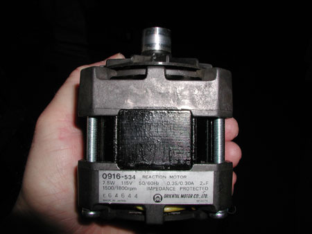
First you need a synchronous motor. This is called an oriental
motor, and is supposed to be synchronous. Even if a motor is 1800
RPM, it may not be synchronous.
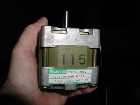
This is another flavor of the same motor, after the fan was removed.
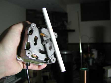
To find out if it is really synchronous, a white plastic tube is taped
to the shaft (really good tape). This allows the exact shaft position
to be known.
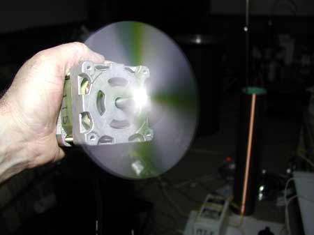
The motor is turned on, and a fluorescent light is shined (shone?)
on the tube. A pattern of four stationary dark bands indicate we
have a synchronous 1800 RPM motor.
Rotating bands would indicate the motor shaft position is not synchronous
with the AC power cycle. A synchronous 3600 RPM motor would have
two such bands.
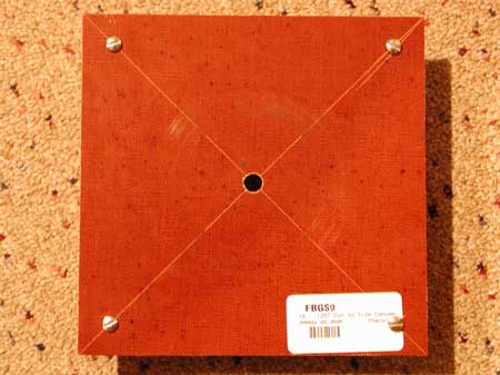
The motor will fit into this 6" square piece of phenolic. The
center hole fits the motor shaft with very little wiggle room. Positions
for the 4 stationary electrodes have been mapped out, holes drilled, and
the electrodes mounted into place. I decided to keep the rotor from
extending beyond the edges of the square, and cut it to 6". The entire
7" electrode could have been accomodated by pushing the stationary electrodes
all the way out.
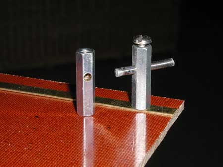
The stationary electrodes are made from 1" lengths of 1/8" tungsten
welding electrode. They are cut from longer rods by scoring with
a file, breaking apart, and then grinding into shape. The electrodes
are held in place using standoffs that have been drilled for the 1/8" rod.
A screw from the bottom holds the standoff in place. A screw from the top
holds the electrode in place.
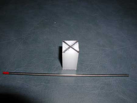
The low inertia rotor is made up of a single tungsten welding electrode
and a 3/4" square length of polyethylene. The 7" electrode has been
cut to a length of 6" since I was too lazy to make a bigger mounting plate
to handle the entire 7" (I could have had the equivalent of a 8" rotor).
The polyethylene provides electrical insulation between the motor shaft
and the spinning electrode.
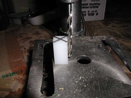
The holes need to be drilled nice and perpendicular if things are to
work well. They cannot break through to each other, or the electrical
isolation will be lost.
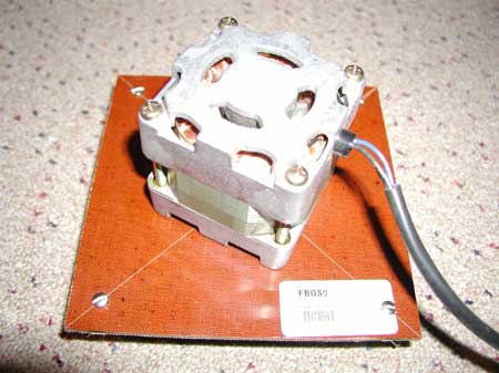
The motor is put into place.

The rotor press fits nicely onto the shaft, after a little of the shaft
was sawed off (too long). The spinning electrode is also press fit.
Two brass strips join the pairs of electrodes into a single switch
that aligns every 90 degrees. Although not a problem, the brass bars
could be located underneath the plate, to discourage discharges from the
rotor.
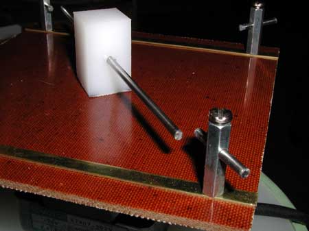
The rotor can be slid up and down to align with the stationary electrodes.
The rotating electrode can be slid back and forth to get it perfectly centered.

The stationary electrodes can be adjusted for alignment and gap.
Typically the gap is kept as small as possible.
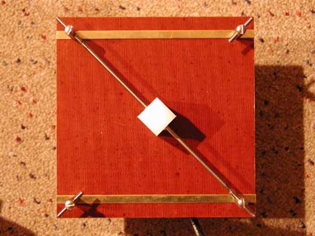
All is aligned and ready to go.
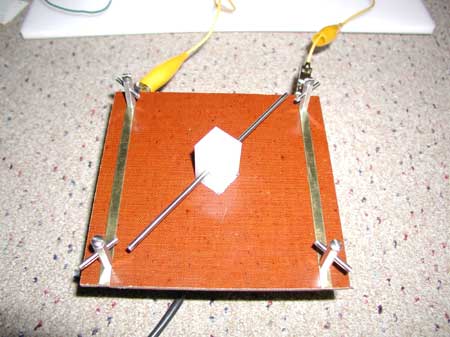
Connection to the SRSG can be made at the brass bars using clamps.
The connection can be improved by extending the bars and drilling holes
for screws. Maybe attach terminals to the screws underneath.
Hmmm, another decision to make.
The stationary electrode plate can be rotated to align at various positions along the AC wave form. The motor could also be mounted securely to the plate in a position of maximum AC voltage. The motor could be mounted to the plate, parallel to the edges, and the rotor adjusted to a position of voltage peak.
A better way to mount the motor and make phase adjustments could be developed someday. But for now, lets fire up some Tesla Coil, synchronous style.
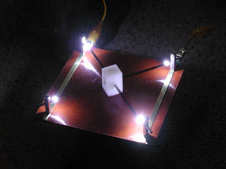
Here is the SRSG in operation. The main light source is the spark
itself, creating the illusion that there are 4 spinning electrodes.
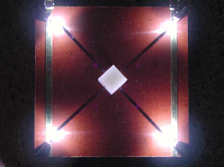
This convincing illusion is not just camera trickery. It really
looks like this. Cool.

Here is the medium size Tesla Coil with the SRSG controlling when the
bangs go off. It is definitely a lot different from the random nature
of a static gap. It sounds meaner.
![]()