Multi-Mini Capacitors
(MMC)
The pulse-energy nature of the Tesla coil has long been a tough environment for the discharge capacitor. Coilers have built capacitors with glass bottles and salt-water, sheets of glass and aluminum foil, and more recently, polyethylene sheets, aluminum flashing, and mineral oil. Professionally built pulse-capacitors were available, but the costs were prohibitive to the average coiler. Although used capacitors (Maxwells) have become readily available on eBay (with unknown remaining life). But the huge currents, voltage spikes, and direct hits from the output-terminal have destroyed many of these capacitors, with only a single infraction.
In the 90's, a new breed of pulse-capacitor was engineered for various commercial applications. These capacitors were designed using metalized-film and polypropylene to achieve a very high dielectric strength and a self-healing nature that could take nearly 3x overvoltage for short periods. Even when an internal breakdown occurred, the poly got punctured, the metal film was vaporized, and the capacitor remained functional. These capacitors could be punctured many times without any noticeable change in performance.
The Tesla coil community quickly discovered these capacitors and determined that they could be hooked up in series-parallel combinations to make any combination of voltage / capacitance that was required. The size was a great improvement over other options, the cost was reasonable, and the performance was as good or better than anything else ever used.
More History of MMC Tesla Coil Capacitors
While I have had minimal problems with these capacitors, there have been some issues.
Issues with GE 42L Series MMC Capacitors
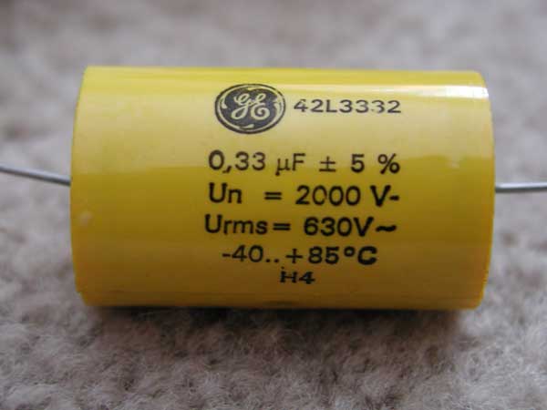
The GE Type 42L (42L3332), metallized polypropylene axial film capacitors utilize a hybrid section
design of polypropylene film, metal foils and metallized polypropylene
dielectric to achieve high peak current ratings. This series is ideal for
high pulse operation and high peak current circuits. It can be obtained
for about $4.00 / capacitor (Allied Electronics).
While rated for 2000 VDC, tests have shown that they can take 5,700 VDC before a puncture occurs. Then,
they recover as if nothing happened. They can be pushed much greater
than the ratings suggest.
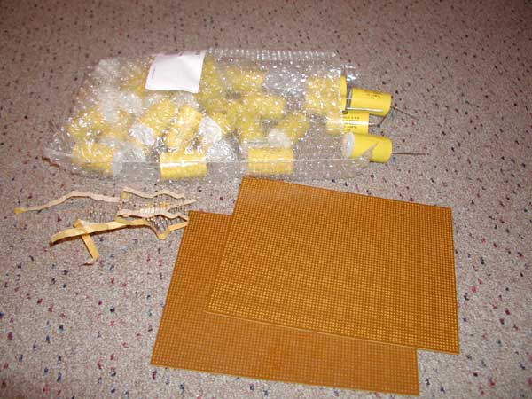
So now what? These capacitors are 0.33 uF and 2000 V. They
need to be hooked up in series to reduce the capacitance and increase the
voltage rating. Here we have a bag of capacitors, several pc boards
for mounting, and a wad of 10 Meg ohm resistors to drain the lethal voltages
after use.
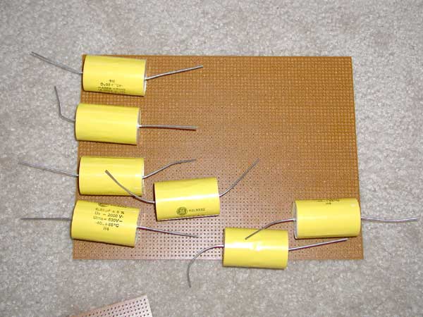
Hmm. It looks like we can fit about 16 capacitors on these pc
boards (4x4 = 16). In series, we have 16 x 2,000 = 32,000 rated volts.
Plugging in the puncture voltage, we have 16 x 5,700 = 91,200 maximum volts.
That should be plenty. The final capacitance is 0.33 uF / 16 = 0.02
uF. Sweet.
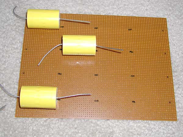
The layout has been marked, but the wire leads are thicker than the
holes in the prefab board. Drilling is required.
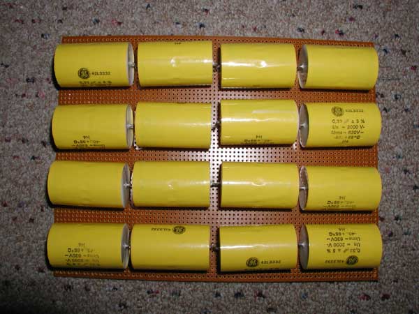
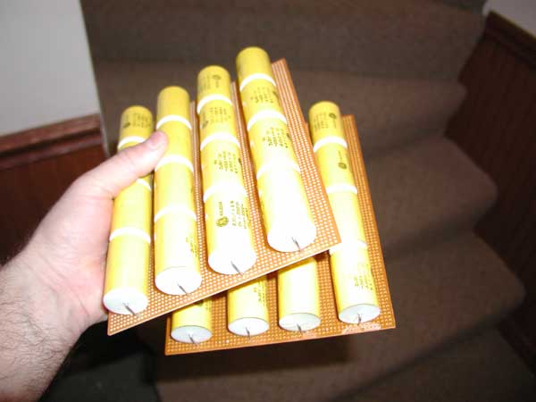
After drilling the holes, bending the leads, and pushing into place,
here's what it looks like.
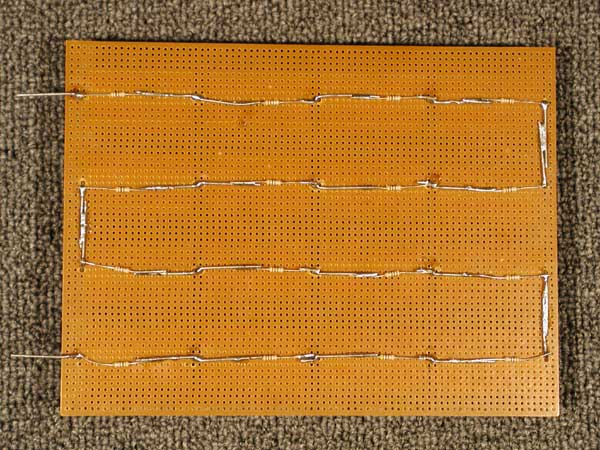
On the back, the series layout can be seen. The output connections
are on the left. A bleeder-resistor is connected across each capacitor.
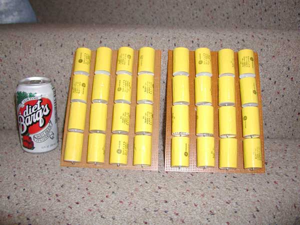
Here's two of them. They can be hooked together for 0.02 x 2
= 0.04 uF for more power. In a magnifier, they can be used in an
equi-drive configuration for 0.02 / 2 = 0.01 uF.
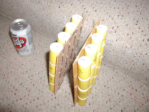
They can be placed back-to-back if separated by a suitable insulator.
The bleeder-resistors drain the leathal voltages within seconds, so
handling is not much of a concern.
They should be nearly indestructible. Yeah baby.
Issues with GE 42L Series MMC Capacitors